- Loading…
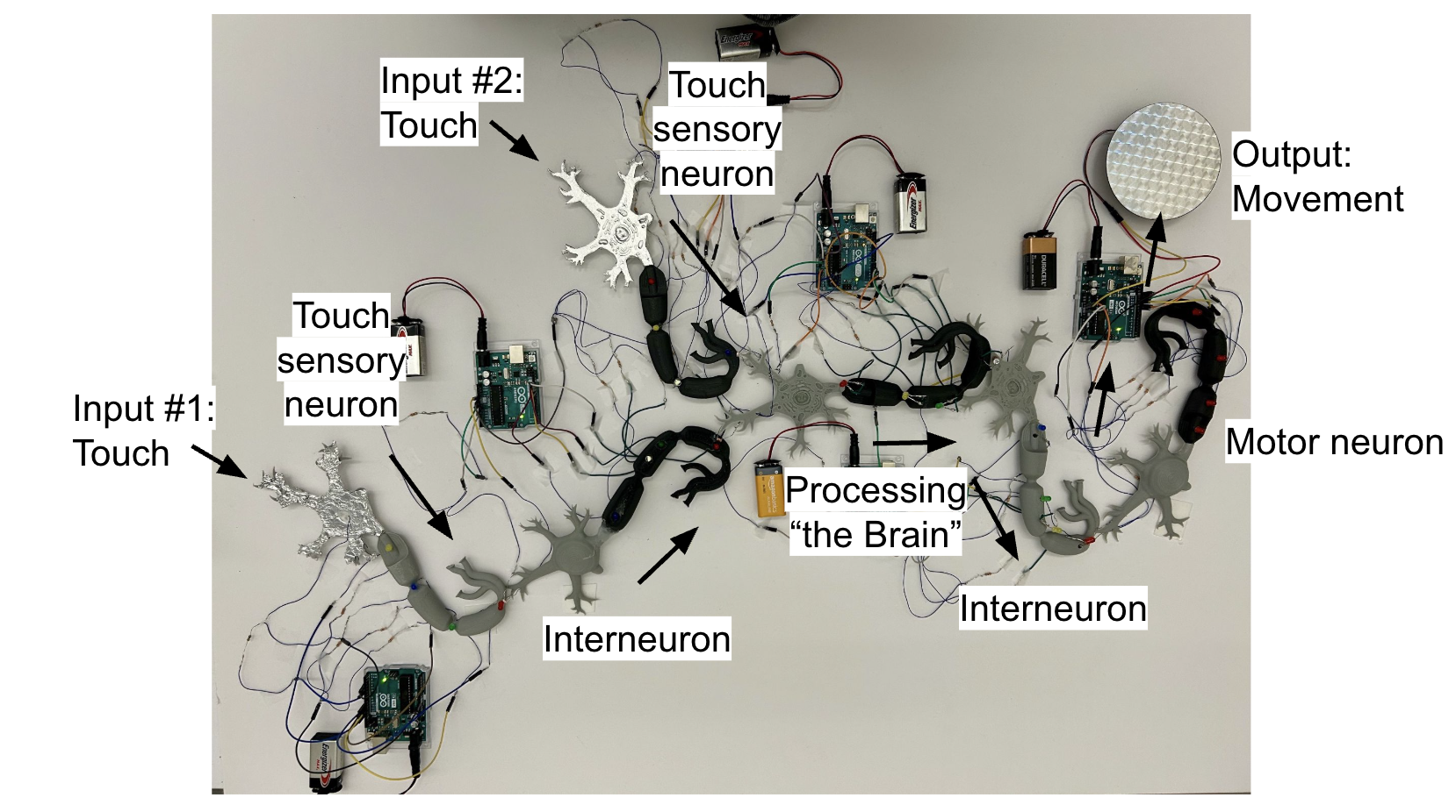
In this project, students will design and build an electronic circuit that mimics the touch sensory system, exploring how neurons communicate through electrical and chemical signaling. Using 3D-printed neuron models, students will practice soldering and transfer their designs from breadboards to sculptural circuitry, blending biology, engineering, and art to deepen their understanding of sensory pathways.
Neuron Model by SpaceKnight: 3D model of a neuron downloaded from Thingiverse; used to build sculptural circuitry (1 per student or group)
Arduino Uno: Microcontroller board used to program and control the circuit (1 per group)
Adafruit MPR121: Capacitive touch sensor breakout board for detecting touch input (1 per 3 groups)
Photoresistors (LDR): Light-sensitive resistors used to simulate sensory input (1 per group)
10kΩ Resistors: Used to limit current or form voltage dividers in the circuit (1 per component that requires it; at least 4 total)
DC Motor: Small motor used to simulate neural output (e.g., movement or feedback) (1 total for motor neuron group)
LEDs: Light-emitting diodes for visual output or signal indication (4 per group, 24 total)
220Ω Resistors: Used to protect LEDs and limit current (4 per group, 25 total)
NPN Transistor (2N2222): Used to control power to components like motors or LEDs (1 total for motor neuron circuit)
Diode (1N4007): Used to protect components from back current when using motors (1 total for motor neuron circuit)
Breadboard Jumper Wires: Male-to-male wires for connecting components on a breadboard (many; assorted per group)
30 AWG Wire: Tin-plated copper wire; solid core, used for permanent connections in sculpture (1 spool per color for class)
Breadboards: Solderless boards used to prototype electronic circuits (1 per group)
Soldering Kit: Includes soldering iron, solder, and tools for creating permanent connections (1 per classroom station)
Drill: Used to drill holes in 3D neuron models for component placement (1 per classroom)
Through this project, students will deepen their appreciation for how complex biological systems can be modeled and understood through hands-on engineering. As they troubleshoot circuits, work with new materials, and translate abstract neural processes into physical forms, students will build confidence in both scientific reasoning and creative problem-solving.
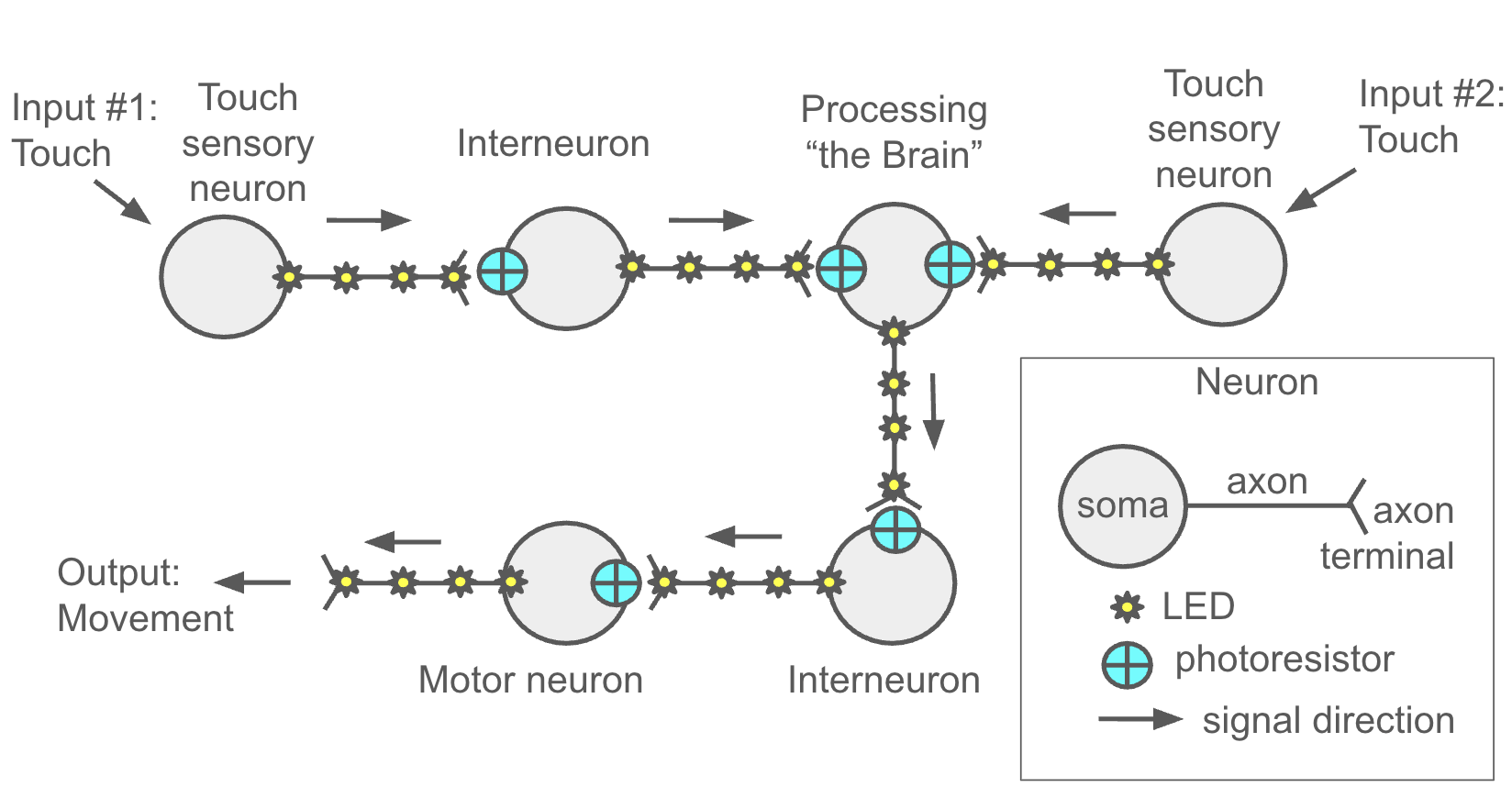
In this lesson, students are introduced to the central dogma of neuroscience—input, processing, output—through discussion and an interactive class simulation. After sharing real-life experiences involving rapid sensory responses (like touching something hot), students review the roles of sensory, processing, interneurons, and motor neurons. The class then acts out a simplified neural pathway, with students representing each type of neuron and passing a signal from input to output. This hands-on activity sets the stage for the main project, where students will design and build electronic circuits that mimic neural communication in the sensory system.
A. Start by asking: “Think of a time you touched something hot—what happened, and how fast did you react?” Let a few students share their experiences.
B. Review the central dogma of neuroscience and definitions:
Briefly explain each step:
Input = Sensory information (external: touch, sound; internal: body temp, hunger)
Processing = Brain or spinal cord analyzing information
Output = Response (movement, speech, change in heart rate, etc.)
C. Introduce three neuron types with quick examples:
D. Class simulation to model a neural circuit. Act out a simplified sensory pathway using students as neurons:
i) Sensory Neurons (2 students):
Each receives a different input stimulus—for example, one reacts to a touch, the other to light. These students pass a physical object (e.g., a small ball or light-up prop) as a signal toward the next step.
ii) Processing Neuron (1 student):
This student represents the brain. They receive input from both sensory neurons and decide how to respond. For example, if both inputs are received, they may trigger a more urgent response; if only one is active, a different or no output might occur.
You can ask this student to “think aloud” (e.g., “Both inputs are active—send a strong signal!”) to model processing.
iii) Interneuron (1 student):
This student simply passes the signal from the processing neuron to the motor neuron—highlighting that interneurons can act as relays, but they aren’t necessarily “thinking” themselves.
iv) Motor Neuron (1 student):
Receives the output signal and carries out a physical response (like jumping, clapping, or shouting “ouch!”).
E. Wrap-up and transition to the project. Explain to the students that they’ll be building electronic circuits to simulate neurons. This will help them understand how circuits can model the sensory processing pathways in the brain.
In this project, students will begin by prototyping their assigned neuron type on a breadboard using provided circuit diagrams, ensuring all components function correctly. Once tested, they will prepare their 3D-printed neuron models by drilling holes and embedding components, then transfer and solder the circuit using 30 AWG wire. After thorough testing and debugging, students will connect their neuron models to form a functioning neural network based on provided pathways. Finally, they’ll explore how changes to the circuit, such as altering outputs or rerouting connections, affect signal transmission and overall behavior, deepening their understanding of neural communication.
1. Prototype on Breadboard
2. Prepare the 3D Neuron Model
3. Transfer Circuit to Neuron Model
4. Final Testing & Debugging
5. Connect and Communicate Between Neurons
6. Explore and Modify
After completing their neuron circuit models, students will document their work through a written and visual explanation. Each group will submit a detailed paragraph along with a circuit diagram that identifies their neuron type, outlines the components used and their functions, and explains how their circuit simulates the behavior of that neuron. The write-up will also include a brief reflection on challenges faced during the design and soldering process, as well as a description of how their neuron connects and communicates within the larger class-wide neural network.
After students have completed the design, testing, and integration of their neuron circuits, assign a written and visual explanation task. Each group will write a detailed write-up and submit a circuit diagram that documents their project.
Students should include the following in their write-up:
Circuit diagram and code for the two touch sensory neurons.
Circuit Diagram:
Code:
#include
#include “Adafruit_MPR121.h”
#ifndef _BV
#define _BV(bit) (1 << (bit))
#endif
Adafruit_MPR121 cap = Adafruit_MPR121();
uint16_t lasttouched = 0;
uint16_t currtouched = 0;
// LED pins
const int ledPins[] = {10, 11, 12, 13};
void setup() {
Serial.begin(9600);
while (!Serial) {
delay(10);
}
Serial.println(“Adafruit MPR121 Capacitive Touch sensor test”);
if (!cap.begin(0x5A)) {
Serial.println(“MPR121 not found, check wiring?”);
while (1);
}
Serial.println(“MPR121 found!”);
// Initialize LED pins
for (int i = 0; i < 4; i++) {
pinMode(ledPins[i], OUTPUT);
digitalWrite(ledPins[i], LOW);
}
}
void loop() {
currtouched = cap.touched();
for (uint8_t i = 0; i < 12; i++) {
if ((currtouched & _BV(i)) && !(lasttouched & _BV(i))) {
Serial.print(“Pad “);
Serial.print(i);
Serial.println(” touched”);
}
if (!(currtouched & _BV(i)) && (lasttouched & _BV(i))) {
Serial.print(“Pad “);
Serial.print(i);
Serial.println(” released”);
}
}
// If touch just started
if (currtouched != 0 && lasttouched == 0) {
Serial.println(“Touch detected – starting LED sequence”);
for (int i = 0; i < 4; i++) {
Serial.print(“Turning on LED “);
Serial.println(i);
digitalWrite(ledPins[i], HIGH);
delay(1000);
digitalWrite(ledPins[i], LOW);
}
Serial.println(“LED sequence complete”);
}
lasttouched = currtouched;
delay(50); // debounce and avoid flooding Serial output
}
Circuit diagram and code for the two interneurons.
Circuit Diagram:
Code:
int animationSpeed = 400; // Speed for LED blinking
int sensorValue = 0; // Value read from the photoresistor
const int sensorPin = A0; // Analog pin connected to the photoresistor
const int ledPins[] = {13, 12, 11, 10}; // LED pins in sequence
const int controlPin = 9; // Output pin for analog control (optional)
void setup() {
// Set LED pins as outputs
for (int i = 0; i < 4; i++) {
pinMode(ledPins[i], OUTPUT);
}
pinMode(sensorPin, INPUT); // Set the photoresistor pin as input
pinMode(controlPin, OUTPUT); // Set the control pin as output
Serial.begin(9600); // Initialize Serial Monitor
}
void loop() {
// Read the value from the photoresistor
sensorValue = analogRead(sensorPin);
// Print the sensor value to the Serial Monitor
Serial.print(“Light Sensor Value: “);
Serial.println(sensorValue);
// Map sensorValue to control brightness (optional)
analogWrite(controlPin, map(sensorValue, 0, 1023, 0, 255));
// If sufficient light is detected, start LED animation
if (sensorValue > 250) { // Adjust threshold as needed
Serial.println(“Light detected! Starting LED animation…”); // Indicate light detection
for (int i = 0; i < 4; i++) {
digitalWrite(ledPins[i], HIGH); // Turn on the LED
delay(animationSpeed); // Wait for the animation speed
digitalWrite(ledPins[i], LOW); // Turn off the LED
delay(animationSpeed); // Wait before the next LED
}
} else {
// If light is below the threshold, turn off all LEDs
Serial.println(“Light level too low, LEDs are off.”); // Indicate low light
for (int i = 0; i < 4; i++) {
digitalWrite(ledPins[i], LOW);
}
}
delay(500); // Delay for stability and readable Serial Monitor output
}
Circuit diagram and code for the processing neuron.
Circuit Diagram:
Code:
int Input0 = 0;
int Input1 = 0;
const int threshold = 1000; // Light threshold for activation
// Define LED pins
const int led1 = 2;
const int led2 = 3;
const int led3 = 4;
const int led4 = 5;
void setup() {
// Setup photoresistors
pinMode(A0, INPUT);
pinMode(A1, INPUT);
// Setup LEDs as outputs
pinMode(led1, OUTPUT);
pinMode(led2, OUTPUT);
pinMode(led3, OUTPUT);
pinMode(led4, OUTPUT);
// Ensure LEDs are initially off
digitalWrite(led1, LOW);
digitalWrite(led2, LOW);
digitalWrite(led3, LOW);
digitalWrite(led4, LOW);
// Start Serial Monitor
Serial.begin(9600);
}
void loop() {
// Read photoresistor values
Input0 = analogRead(A0);
Input1 = analogRead(A1);
// Print sensor values for debugging
Serial.print(“Photoresistor 1: “);
Serial.print(Input0);
Serial.print(” | Photoresistor 2: “);
Serial.println(Input1);
// Check if either sensor detects light above the threshold
if (Input0 > threshold || Input1 > threshold) {
digitalWrite(led1, HIGH);
delay(500);
digitalWrite(led2, HIGH);
delay(500);
digitalWrite(led3, HIGH);
delay(500);
digitalWrite(led4, HIGH);
delay(5000); // Keep LEDs on for 5 seconds
}
else {
// Turn off all LEDs if neither sensor detects light
digitalWrite(led1, LOW);
digitalWrite(led2, LOW);
digitalWrite(led3, LOW);
digitalWrite(led4, LOW);
}
}
Circuit diagram and code for the motor neuron and motor output.
Circuit Diagram:
Code:
int sensorState = 0;
void setup() {
// put your setup code here, to run once:
pinMode(13, OUTPUT);
pinMode(12, OUTPUT);
pinMode(11, OUTPUT);
pinMode(10, OUTPUT);
pinMode(9, OUTPUT);
pinMode (A0, INPUT);
Serial.begin(9800);
}
void loop()
{
sensorState = analogRead(A0);
Serial.print(“Sensor State: “);
Serial.println(sensorState);
;if(sensorState>300 && sensorState<1023)
{
digitalWrite(9, HIGH);
delay(500);
digitalWrite(10, HIGH);
delay(500);
digitalWrite(11, HIGH);
delay(500);
digitalWrite(12, HIGH);
delay(500);
digitalWrite(9, LOW);
delay(100);
digitalWrite(10, LOW);
delay(100);
digitalWrite(11, LOW);
delay(100);
digitalWrite(12, LOW);
delay(100);
digitalWrite(13, HIGH);
delay(10000);
digitalWrite(13, LOW);
}
else
{
}
}
Having trouble? Let us know by completing the form below. We'll do our best to get your issues resolved quickly.
"*" indicates required fields


