- Loading…
In this one-week lesson, students aged 14 and older will learn to design and build a rover from scratch, focusing on electronic circuit creation using Arduino Nano and C++ programming. The week will encompass various disciplines, including basic electronics concepts, programming for motor and sensor control, 3D design using CAD software, and 3D printing of rover components. Students will assemble their rovers by integrating the electronic circuits with the printed parts, followed by testing and troubleshooting. The lesson culminates in presentations where students demonstrate their rovers’ functionality, showcasing their hands-on learning experience in robotics and engineering.
4o mini
With these materials and tools, students will have everything they need to successfully design, program, and build their rovers throughout the course.
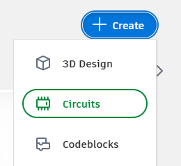
Objective: This lesson will introduce you to basic electronics and programming concepts using C++. You will learn to control an LED, a servo motor, and an ultrasonic distance sensor
Instructions:

Notes:
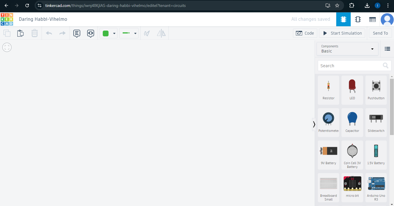
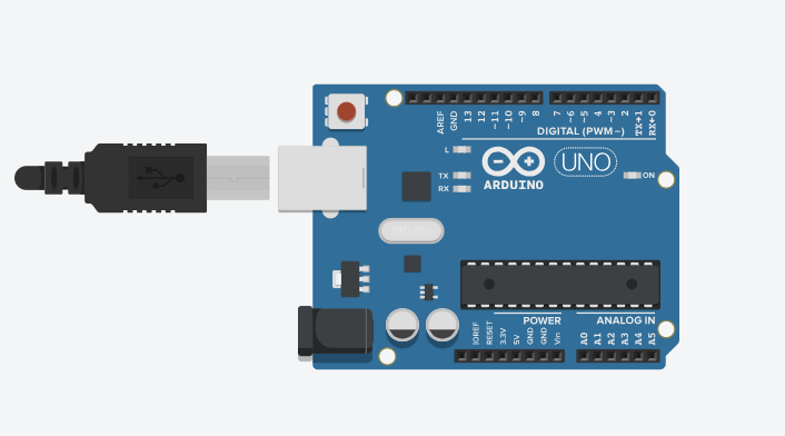
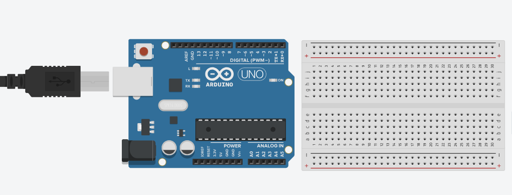
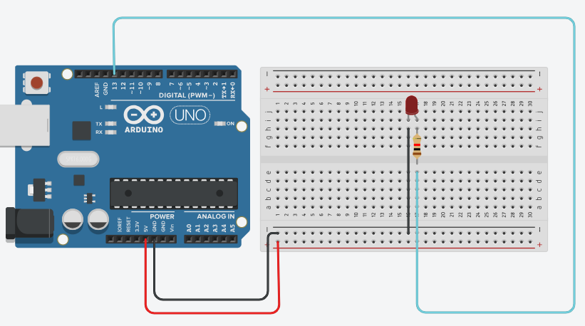
Connecting the LED:
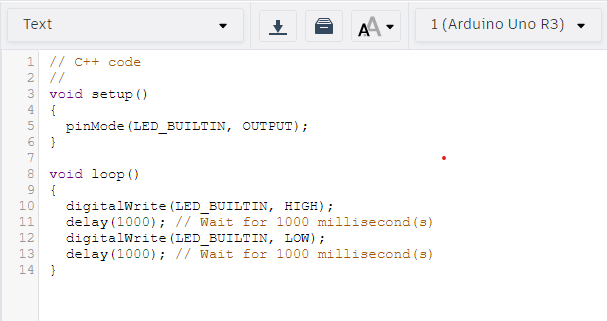
Copy and paste this code into the code editor:
int ledPin = 13; // Define pin 13 as the LED pin
void setup() {
pinMode(ledPin, OUTPUT); // Set the LED pin as an output pin
}
void loop() {
digitalWrite(ledPin, HIGH); // Turn the LED on
delay(1000); // Wait for one second
digitalWrite(ledPin, LOW); // Turn the LED off
delay(1000); // Wait for one second
}
Code explanation:
–int ledPin = 13; defines the pin number for the LED.
–pinMode(ledPin, OUTPUT); sets the pin as an output.
–digitalWrite(ledPin, HIGH); turns the LED on.
–delay(1000); pauses the program for one second.
–digitalWrite(ledPin, LOW); turns the LED off.
Notes:
Modify the code to include serial communication that tracks the LED’s state:
Copy and paste code into the code editotor
int ledPin = 13; // Define pin 13 as the LED pin
void setup() {
pinMode(ledPin, OUTPUT); // Set the LED pin as an output
Serial.begin(9600); // Initialize serial communication at 9600 baud
}
void loop() {
digitalWrite(ledPin, HIGH); // Turn the LED on
Serial.print(“LED State: “); // Print label for clarity
Serial.println(“ON”); // Print LED state and move to new line
delay(1000); // Wait for one second
digitalWrite(ledPin, LOW); // Turn the LED off
Serial.print(“LED State: “); // Print label for clarity
Serial.println(“OFF”); // Print LED state and move to new line
delay(1000); // Wait for one second
}
Code explanation:
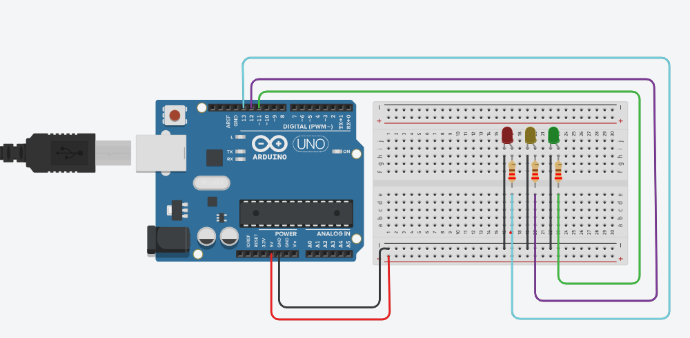
-Place two more LEDs on the breadboard.
-Connect their cathodes to digital pins 12 and 11 on the Arduino.
-Connect their anodes to 220Ω resistors, then to GND on the Arduino.
-After pasting the code, click “Start Simulation” to run the program and test the circuit.
Copy and paste the code in to the code editor.
int ledPin1 = 13; // First LED
int ledPin2 = 12; // Second LED
int ledPin3 = 11; // Third LED
void setup() {
pinMode(ledPin1, OUTPUT); // Set pin 13 as an output
pinMode(ledPin2, OUTPUT); // Set pin 12 as an output
pinMode(ledPin3, OUTPUT); // Set pin 11 as an output
Serial.begin(9600); // Start serial communication at 9600 baud
}
void loop() {
digitalWrite(ledPin1, HIGH); // Turn the first LED on
digitalWrite(ledPin2, HIGH); // Turn the second LED on
digitalWrite(ledPin3, HIGH); // Turn the third LED on
Serial.println(“All LEDs ON”); // Print message to Serial Monitor
delay(1000); // Wait for one second
digitalWrite(ledPin1, LOW); // Turn the first LED off
digitalWrite(ledPin2, LOW); // Turn the second LED off
digitalWrite(ledPin3, LOW); // Turn the third LED off
Serial.println(“All LEDs OFF”); // Print message to Serial Monitor
delay(1000); // Wait for one second
}
Code explanation:
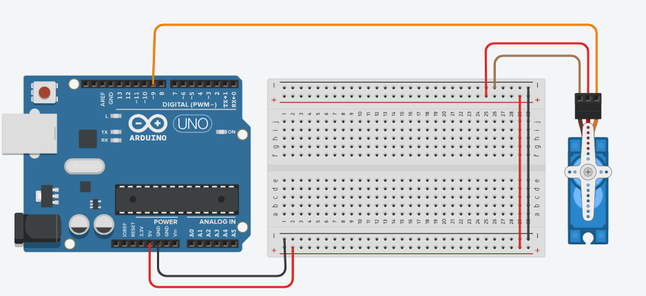
Connect the Servo:
Copy and paste the code into the code editor
int servoPin = 9; // Define pin 9 for the servo motor
#include <Servo.h> // Include the Servo library
Servo myServo; // Create a Servo object
void setup() {
myServo.attach(servoPin); // Attach the servo to pin 9
Serial.begin(9600); // Initialize serial communication at 9600 baud
}
void loop() {
myServo.write(0); // Turn the servo to 0 degrees
Serial.print(“Servo angle: “); // Print label for clarity
Serial.println(“0 degrees”); // Print the current angle
delay(1000); // Wait for one second
myServo.write(90); // Turn the servo to 90 degrees
Serial.print(“Servo angle: “); // Print label for clarity
Serial.println(“90 degrees”); // Print the current angle
delay(1000); // Wait for one second
myServo.write(180); // Turn the servo to 180 degrees
Serial.print(“Servo angle: “); // Print label for clarity
Serial.println(“180 degrees”); // Print the current angle
delay(1000); // Wait for one second
}
Code explanation:
Notes:
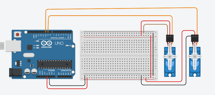
Connect the Second Servo:
Copy and paste this code into the code editor
#include <Servo.h> // Include the Servo library
int servoPin1 = 9; // Define pin 9 for the first servo motor
int servoPin2 = 10; // Define pin 10 for the second servo motor
Servo myServo1; // Create a Servo object for the first servo motor
Servo myServo2; // Create a Servo object for the second servo motor
void setup() {
myServo1.attach(servoPin1); // Attach the first servo to pin 9
myServo2.attach(servoPin2); // Attach the second servo to pin 10
Serial.begin(9600); // Initialize serial communication
}
void loop() {
myServo1.write(0); // Move the first servo to 0 degrees
myServo2.write(0); // Move the second servo to 0 degrees
Serial.print(“Servo 1 angle: “);
Serial.println(“0 degrees”); // Print the angle of the first servo
Serial.print(“Servo 2 angle: “);
Serial.println(“0 degrees”); // Print the angle of the second servo
delay(1000); // Wait for one second
myServo1.write(90); // Move the first servo to 90 degrees
myServo2.write(90); // Move the second servo to 90 degrees
Serial.print(“Servo 1 angle: “);
Serial.println(“90 degrees”); // Print the angle of the first servo
Serial.print(“Servo 2 angle: “);
Serial.println(“90 degrees”); // Print the angle of the second servo
delay(1000); // Wait for one second
myServo1.write(180); // Move the first servo to 180 degrees
myServo2.write(180); // Move the second servo to 180 degrees
Serial.print(“Servo 1 angle: “);
Serial.println(“180 degrees”); // Print the angle of the first servo
Serial.print(“Servo 2 angle: “);
Serial.println(“180 degrees”); // Print the angle of the second servo
delay(1000); // Wait for one second
}
Code Explanation:
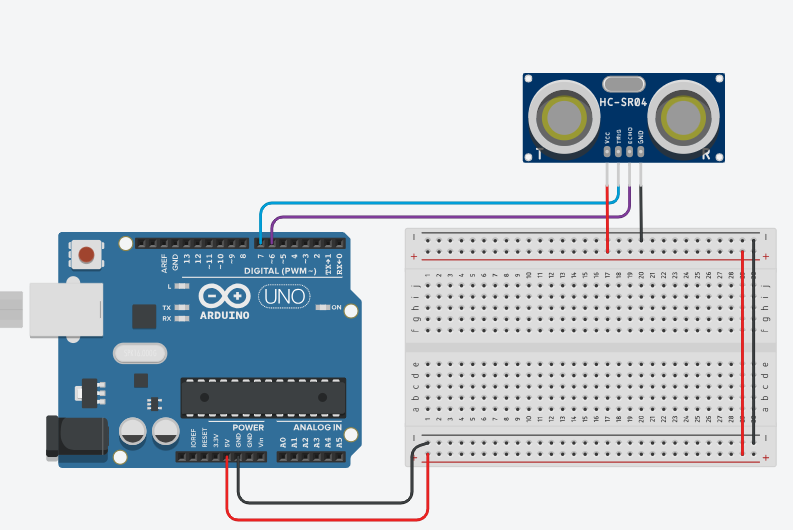
Connect the Ultrasonic Sensor:
Copy and paste the code in the code editor:
int trigPin = 7; // Trig pin for sending out sound waves
int echoPin = 6; // Echo pin for receiving sound waves
long duration; // Variable to store the time it takes for the echo to return
int distance; // Variable to store the calculated distance
void setup() {
pinMode(trigPin, OUTPUT); // Set the Trig pin as output
pinMode(echoPin, INPUT); // Set the Echo pin as input
Serial.begin(9600); // Begin serial communication for debugging
}
void loop() {
digitalWrite(trigPin, LOW); // Make sure the Trig pin is low
delayMicroseconds(2); // Wait for 2 microseconds
digitalWrite(trigPin, HIGH); // Send a sound wave pulse
delayMicroseconds(10); // Wait for 10 microseconds
digitalWrite(trigPin, LOW); // Stop sending the pulse
duration = pulseIn(echoPin, HIGH); // Measure the duration of the echo
distance = duration * 0.034 / 2; // Calculate distance in cm
Serial.print(“Distance: “); // Print the distance to the Serial Monitor
Serial.print(distance);
Serial.println(” cm”);
delay(500); // Wait half a second before measuring again
}
Code explanation:
Notes:
-Add a servo to the existing circuit.
-Update the existing code to control the newly added servo motor based on the distance measured by the ultrasonic sensor. The servo’s position will adjust according to the distance detected by the ultrasonic sensor.
Code:
#include <Servo.h>
Servo servo1;
int servoPin = 6;
int echoPin = 3;
int trigPin = 5;
long duration;
int distance;
void setup() {
servo1.attach(servoPin);
pinMode(trigPin, OUTPUT);
pinMode(echoPin, INPUT);
Serial.begin(9600);
}
void loop() {
// Trigger the ultrasonic sensor
digitalWrite(trigPin, LOW);
delayMicroseconds(2);
digitalWrite(trigPin, HIGH);
delayMicroseconds(10);
digitalWrite(trigPin, LOW);
// Read the echo
duration = pulseIn(echoPin, HIGH);
// Calculate the distance
distance = duration * 0.034 / 2;
// Print the distance to the serial monitor
Serial.print(“Distance: “);
Serial.print(distance);
Serial.println(” cm”);
// Control the servo based on the distance
if (distance < 20) {
Serial.println(“Angle 90”);
servo1.write(90); // Move the servo to 90 degrees
delay(1000);
} else if (distance > 20) {
Serial.println(“Angle 0”);
servo1.write(0); // Move the servo to 0 degrees
}
delay(500); // Delay between measurements
}
Code explanation:
The servo motor now moves to different angles based on the distance measured by the ultrasonic sensor.
If the distance is less than 20 cm, the servo moves to 0 degrees.
If the distance is between 20 and 50 cm, the servo moves to 90 degrees.
If the distance is more than 50 cm, the servo moves to 180 degrees.
Connect the LED:
Code:
int ledPin = 13; // Pin for the LED
int trigPin = 7; // Pin for the ultrasonic sensor’s trigger
int echoPin = 6; // Pin for the ultrasonic sensor’s echo
long duration; // Variable to store the time of the echo
int distance; // Variable to store the calculated distance
void setup() {
pinMode(ledPin, OUTPUT); // Set the LED pin as an output
pinMode(trigPin, OUTPUT); // Set the trigger pin as an output
pinMode(echoPin, INPUT); // Set the echo pin as an input
Serial.begin(9600); // Initialize serial communication at 9600 baud
}
void loop() {
// Send a pulse from the trigger pin
digitalWrite(trigPin, LOW);
delayMicroseconds(2);
digitalWrite(trigPin, HIGH);
delayMicroseconds(10);
digitalWrite(trigPin, LOW);
// Measure the duration of the echo
duration = pulseIn(echoPin, HIGH);
// Calculate distance in cm
distance = duration * 0.034 / 2;
// Print distance to Serial Monitor
Serial.print(“Distance: “);
Serial.print(distance);
Serial.println(” cm”);
// Control the LED based on the distance
if (distance < 20) { // If the object is closer than 20 cm
digitalWrite(ledPin, HIGH); // Turn the LED on
} else {
digitalWrite(ledPin, LOW); // Turn the LED off
}
delay(500); // Wait half a second before taking another measurement
}
Code explanation:
Objective :This lesson focuses on controlling a DC motor with an Arduino and an L293D motor driver in Tinkercad. It includes wiring the DC motor and motor driver to the Arduino, and writing code to control the motor's direction . The lesson demonstrates simulating the motor's operation, emphasizing basic motor control and circuit design skills.
Instructions:
Notes:
Place the motor driver on the breadboard:
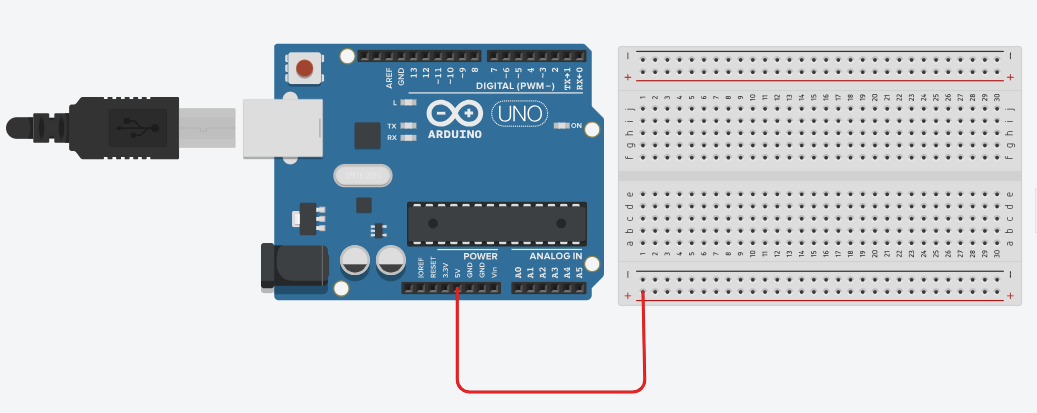
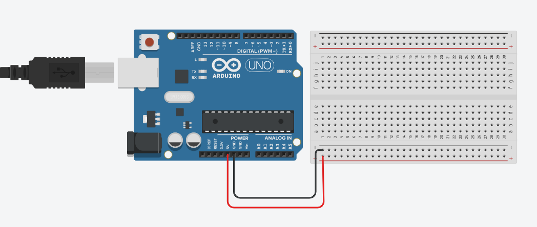
Power the motor driver and breadboard:
Copy and paste the code:
int motorPin1 = 9; // Control pin 1 for the motor
int motorPin2 = 10; // Control pin 2 for the motor
int enablePin = 6; // PWM pin for motor speed control
void setup() {
pinMode(motorPin1, OUTPUT); // Set motor control pin 1 as an output
pinMode(motorPin2, OUTPUT); // Set motor control pin 2 as an output
pinMode(enablePin, OUTPUT); // Set the enable pin as an output
}
void loop() {
analogWrite(enablePin, 255); // Set motor speed to maximum (255)
digitalWrite(motorPin1, HIGH); // Set IN1 high
digitalWrite(motorPin2, LOW); // Set IN2 low
delay(2000); // Run the motor for 2 seconds
digitalWrite(motorPin1, LOW); // Stop the motor
digitalWrite(motorPin2, LOW); // Stop the motor
delay(2000); // Wait for 2 seconds
}
Code Explanation:
void setup()
void loop()
Place the push button on the breadboard:
Add a 10k ohm pull-up resistor:
Copy and paste this code into the code editor:
int motorPin1 = 9; // Control pin 1 for the motor
int motorPin2 = 8; // Control pin 2 for the motor
int enablePin = 6; // Enable pin for motor speed control
int buttonPin = 7; // Button pin
void setup() {
pinMode(motorPin1, OUTPUT); // Set motor control pin 1 as an output
pinMode(motorPin2, OUTPUT); // Set motor control pin 2 as an output
pinMode(enablePin, OUTPUT); // Set enable pin as an output
pinMode(buttonPin, INPUT_PULLUP); // Set the button pin as an input with an internal pull-up resistor
}
void loop() {
int buttonState = digitalRead(buttonPin); // Read the button state
if (buttonState == LOW) { // If button is pressed
digitalWrite(motorPin1, HIGH); // Set IN1 high to turn the motor on
digitalWrite(motorPin2, LOW); // Set IN2 low
analogWrite(enablePin, 255); // Set the motor speed to maximum (255)
} else {
digitalWrite(motorPin1, LOW); // Set both IN1 and IN2 low to stop the motor
digitalWrite(motorPin2, LOW);
analogWrite(enablePin, 0); // Turn off the motor (speed 0)
}
}
Code Explanation:
pinMode(motorPin1, OUTPUT);: Sets pin 9 as an output to control the motor.
pinMode(motorPin2, OUTPUT);: Sets pin 8 as an output to control the motor.
pinMode(buttonPin, INPUT_PULLUP);: Sets pin 7 as an input with a pull-up resistor
(button press reads LOW).
int buttonState = digitalRead(buttonPin);: Reads whether the button is pressed (LOW)
or not (HIGH).
if (buttonState == LOW) { … }: If the button is pressed:
digitalWrite(motorPin1, HIGH);: Turns on the motor by setting pin 9 high.
digitalWrite(motorPin2, LOW);: Ensures pin 8 is low, so the motor runs in one direction.
else { … }: If the button is not pressed:
digitalWrite(motorPin1, LOW);: Stops the motor by setting pin 9 low.
digitalWrite(motorPin2, LOW);: Ensures pin 8 is also low, stopping the motor.
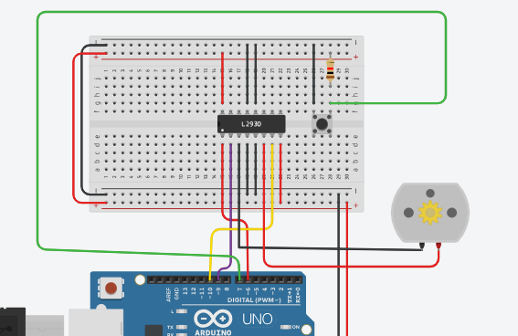
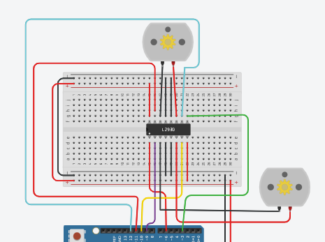
Add the second motor to the breadboard:
Connect the second motor’s terminals to the motor driver’s OUT3 and OUT4.
Connect motor driver inputs to Arduino:
-Connect IN3 and IN4 of the motor driver to Arduino pins 11 and 12.
The second motor will share the power lines already connected to the 5V and GND rails of the breadboard.
Copy and paste the code into the code editor:
int motorPin1 = 9; // Control pin 1 for the first motor
int motorPin2 = 8; // Control pin 2 for the first motor
int motorPin3 = 11; // Control pin 1 for the second motor
int motorPin4 = 12; // Control pin 2 for the second motor
int enablePin1 = 6; // Enable pin for the first motor
int enablePin2 = 3; // Enable pin for the second motor
int buttonPin = 7; // Button pin
void setup() {
pinMode(motorPin1, OUTPUT); // Set motor control pin 1 for the first motor as an output
pinMode(motorPin2, OUTPUT); // Set motor control pin 2 for the first motor as an output
pinMode(motorPin3, OUTPUT); // Set motor control pin 1 for the second motor as an output
pinMode(motorPin4, OUTPUT); // Set motor control pin 2 for the second motor as an output
pinMode(enablePin1, OUTPUT); // Set enable pin for the first motor as an output
pinMode(enablePin2, OUTPUT); // Set enable pin for the second motor as an output
pinMode(buttonPin, INPUT_PULLUP); // Set the button pin as an input with an internal pull-up resistor
}
void loop() {
int buttonState = digitalRead(buttonPin); // Read the button state
if (buttonState == LOW) { // If button is pressed
// First motor control
digitalWrite(motorPin1, HIGH); // Set IN1 high to turn the first motor on
digitalWrite(motorPin2, LOW); // Set IN2 low for the first motor
analogWrite(enablePin1, 255); // Set the first motor speed to maximum
// Second motor control
digitalWrite(motorPin3, HIGH); // Set IN3 high to turn the second motor on
digitalWrite(motorPin4, LOW); // Set IN4 low for the second motor
analogWrite(enablePin2, 255); // Set the second motor speed to maximum
} else {
// Stop both motors
digitalWrite(motorPin1, LOW); // Set both IN1 and IN2 low to stop the first motor
digitalWrite(motorPin2, LOW);
analogWrite(enablePin1, 0); // Stop the first motor
digitalWrite(motorPin3, LOW); // Set both IN3 and IN4 low to stop the second motor
digitalWrite(motorPin4, LOW);
analogWrite(enablePin2, 0); // Stop the second motor
}
}
Code explanation:
pinMode(): Configures motor pins as outputs and the button pin as an input with an
internal pull-up resistor
buttonState: Reads the button state.
If the button is pressed (LOW), both motors turn on (motorPin1 and motorPin3 set
HIGH).
If not pressed, both motors stop (all motor pins set LOW).
Code:
// MOTOR 1
int motor1enA = 9; // PWM Speed Control (ENA connected to pin 9)
int motor1in1 = 8; // Direction Control (IN1 connected to pin 8)
int motor1in2 = 7; // Direction Control (IN2 connected to pin 7)
// MOTOR 2
int motor2enB = 10; // PWM Speed Control (ENB connected to pin 10)
int motor2in3 = 6; // Direction Control (IN3 connected to pin 6)
int motor2in4 = 5; // Direction Control (IN4 connected to pin 5)
// Serial Communication
int state;
void setup() {
// Start serial communication
Serial.begin(9600);
// MOTOR 1 OUTPUTS
pinMode(motor1enA, OUTPUT);
pinMode(motor1in1, OUTPUT);
pinMode(motor1in2, OUTPUT);
// MOTOR 2 OUTPUTS
pinMode(motor2enB, OUTPUT);
pinMode(motor2in3, OUTPUT);
pinMode(motor2in4, OUTPUT);
// Set initial motor speed
analogWrite(motor1enA, 100); // Set speed (0-255)
analogWrite(motor2enB, 100); // Set speed (0-255)
}
// Function to start both motors (forward direction)
void startMotors() {
digitalWrite(motor1in1, HIGH);
digitalWrite(motor1in2, LOW);
digitalWrite(motor2in3, HIGH);
digitalWrite(motor2in4, LOW);
}
// Function to stop both motors
void stopMotors() {
digitalWrite(motor1in1, LOW);
digitalWrite(motor1in2, LOW);
digitalWrite(motor2in3, LOW);
digitalWrite(motor2in4, LOW);
}
void loop() {
// Serial control for starting and stopping motors
if (Serial.available() > 0) {
state = Serial.read();
if (state == ‘S’) {
Serial.println(“Stop Motors”);
stopMotors();
} else if (state == ‘F’) {
Serial.println(“Start Motors”);
startMotors();
}
}
}
Explanation:
Motor 1:
Motor 2:
motor2in3 = 6, motor2in4 = 5: These control the direction of Motor 2 in the same way
as Motor 1.
Motor Control Functions:
Void loop() :
Serial.available() > 0: Checks if there’s data in the serial buffer (i.e., a character has been sent from the Serial Monitor).
Serial.read(): Reads the incoming data and stores it in the state variable.
If the received character is ‘S’, the motors stop, and the message “Stop Motors” is printed.
If the received character is ‘F’, the motors start moving forward, and the message “Start Motors” is printed.
// MOTOR 1
int motor1enA = 9; // PWM Speed Control (ENA connected to pin 9)
int motor1in1 = 8; // Direction Control (IN1 connected to pin 8)
int motor1in2 = 7; // Direction Control (IN2 connected to pin 7)
// MOTOR 2
int motor2enB = 10; // PWM Speed Control (ENB connected to pin 10)
int motor2in3 = 6; // Direction Control (IN3 connected to pin 6)
int motor2in4 = 5; // Direction Control (IN4 connected to pin 5)
// Serial Communication
int state;
void setup() {
// Start serial communication
Serial.begin(9600);
// MOTOR 1 OUTPUTS
pinMode(motor1enA, OUTPUT);
pinMode(motor1in1, OUTPUT);
pinMode(motor1in2, OUTPUT);
// MOTOR 2 OUTPUTS
pinMode(motor2enB, OUTPUT);
pinMode(motor2in3, OUTPUT);
pinMode(motor2in4, OUTPUT);
}
// Function to set motor speed and enable them
void startMotors() {
// Set motor speeds (range: 0 – 255)
analogWrite(motor1enA, 100); // Motor 1 speed
analogWrite(motor2enB, 100); // Motor 2 speed
Serial.println(“Motors started”);
}
// Function to move forward
void forward() {
digitalWrite(motor1in1, HIGH);
digitalWrite(motor1in2, LOW);
digitalWrite(motor2in3, HIGH);
digitalWrite(motor2in4, LOW);
}
// Function to move backward
void backward() {
digitalWrite(motor1in1, LOW);
digitalWrite(motor1in2, HIGH);
digitalWrite(motor2in3, LOW);
digitalWrite(motor2in4, HIGH);
}
// Function to turn left (by rotating only Motor 1)
void left() {
digitalWrite(motor1in1, HIGH);
digitalWrite(motor1in2, LOW);
digitalWrite(motor2in3, LOW);
digitalWrite(motor2in4, LOW);
}
// Function to turn right (by rotating only Motor 2)
void right() {
digitalWrite(motor1in1, LOW);
digitalWrite(motor1in2, LOW);
digitalWrite(motor2in3, HIGH);
digitalWrite(motor2in4, LOW);
}
// Function to stop both motors
void stopM() {
digitalWrite(motor1in1, LOW);
digitalWrite(motor1in2, LOW);
digitalWrite(motor2in3, LOW);
digitalWrite(motor2in4, LOW);
}
void loop() {
// Check if there is serial input
if (Serial.available() > 0) {
state = Serial.read(); // Read the input character
// Motor control based on serial input
if (state == ‘T’) {
Serial.println(“Start Motors”);
startMotors();
} else if (state == ‘F’) {
Serial.println(“Go Forward”);
forward();
} else if (state == ‘B’) {
Serial.println(“Go Backward”);
backward();
} else if (state == ‘L’) {
Serial.println(“Go Left”);
left();
} else if (state == ‘R’) {
Serial.println(“Go Right”);
right();
} else if (state == ‘S’) {
Serial.println(“Stop”);
stopM();
}
}
}
Open the Serial Monitor: In your Tinkercad circuit, click on the “Start Simulation” button. Then, click on the “Serial Monitor” button (a small icon resembling a magnifying glass or monitor) at the top right of the simulation window.
Send Commands: Type one of the following commands in the input field and press Enter:
‘T’: Start the motors at the initial speed.
‘F’: Move the motors forward.
‘B’: Move the motors backward.
‘L’: Turn left by rotating Motor 1.
‘R’: Turn right by rotating Motor 2.
‘S’: Stop both motors.
Objective:In this lesson, learners will transition from virtual circuit design to real-world implementation by building and testing circuits previously designed in Tinkercad. This will involve assembling components on a breadboard, wiring connections, and troubleshooting to ensure correct functionality in a physical environment. The lesson emphasizes applying theoretical knowledge to practical tasks and highlights the importance of practical testing in electronics.
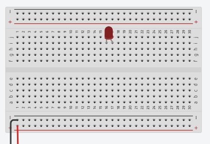
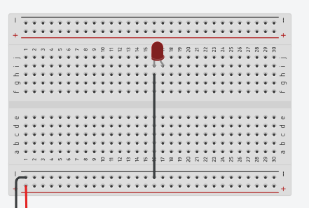
Connect the LED
Copy and paste the following code into the Arduino IDE:
ledPin = 13; // Define pin 13 as the LED pin
void setup() {
pinMode(ledPin, OUTPUT); // Set the LED pin as an output pin
Serial.begin(9600); // Initialize serial communication at 9600 baud rate
}
void loop() {
digitalWrite(ledPin, HIGH); // Turn the LED on
Serial.println(“LED is ON”); // Print message to serial monitor
delay(1000); // Wait for one second
digitalWrite(ledPin, LOW); // Turn the LED off
Serial.println(“LED is OFF”); // Print message to serial monitor
delay(1000); // Wait for one second
}
Click on the upload button in the Arduino IDE to upload the code to your Arduino board.
Observe the LED blinking on and off.
Connect Additional LEDs
Copy and paste the following code into the Arduino IDE:
int ledPin1 = 13; // First LED
int ledPin2 = 12; // Second LED
int ledPin3 = 11; // Third LED
void setup() {
pinMode(ledPin1, OUTPUT); // Set pin 13 as an output
pinMode(ledPin2, OUTPUT); // Set pin 12 as an output
pinMode(ledPin3, OUTPUT); // Set pin 11 as an output
Serial.begin(9600); // Initialize serial communication at 9600 baud rate
}
void loop() {
digitalWrite(ledPin1, HIGH); // Turn the first LED on
digitalWrite(ledPin2, HIGH); // Turn the second LED on
digitalWrite(ledPin3, HIGH); // Turn the third LED on
Serial.println(“All LEDs are ON”); // Print message to serial monitor
delay(1000); // Wait for one second
digitalWrite(ledPin1, LOW); // Turn the first LED off
digitalWrite(ledPin2, LOW); // Turn the second LED off
digitalWrite(ledPin3, LOW); // Turn the third LED off
Serial.println(“All LEDs are OFF”); // Print message to serial monitor
delay(1000); // Wait for one second
}
Click on the upload button in the Arduino IDE to upload the code.
Observe the three LEDs blinking on and off together.
Connect the Servo:
int servoPin = 9; // Define pin 9 for the servo motor
#include <Servo.h> // Include the Servo library
Servo myServo; // Create a Servo object
void setup() {
myServo.attach(servoPin); // Attach the servo to pin 9
Serial.begin(9600); // Initialize serial communication at 9600 baud
}
void loop() {
myServo.write(0); // Turn the servo to 0 degrees
Serial.print(“Servo angle: “); // Print label for clarity
Serial.println(“0 degrees”); // Print the current angle
delay(1000); // Wait for one second
myServo.write(90); // Turn the servo to 90 degrees
Serial.print(“Servo angle: “); // Print label for clarity
Serial.println(“90 degrees”); // Print the current angle
delay(1000); // Wait for one second
myServo.write(180); // Turn the servo to 180 degrees
Serial.print(“Servo angle: “); // Print label for clarity
Serial.println(“180 degrees”); // Print the current angle
delay(1000); // Wait for one second
}
Connect the Second Servo:
#include <Servo.h> // Include the Servo library
int servoPin1 = 9; // Define pin 9 for the first servo motor
int servoPin2 = 10; // Define pin 10 for the second servo motor
Servo myServo1; // Create a Servo object for the first servo motor
Servo myServo2; // Create a Servo object for the second servo motor
void setup() {
myServo1.attach(servoPin1); // Attach the first servo to pin 9
myServo2.attach(servoPin2); // Attach the second servo to pin 10
Serial.begin(9600); // Initialize serial communication
}
void loop() {
myServo1.write(0); // Move the first servo to 0 degrees
myServo2.write(0); // Move the second servo to 0 degrees
Serial.print(“Servo 1 angle: “);
Serial.println(“0 degrees”); // Print the angle of the first servo
Serial.print(“Servo 2 angle: “);
Serial.println(“0 degrees”); // Print the angle of the second servo
delay(1000); // Wait for one second
myServo1.write(90); // Move the first servo to 90 degrees
myServo2.write(90); // Move the second servo to 90 degrees
Serial.print(“Servo 1 angle: “);
Serial.println(“90 degrees”); // Print the angle of the first servo
Serial.print(“Servo 2 angle: “);
Serial.println(“90 degrees”); // Print the angle of the second servo
delay(1000); // Wait for one second
myServo1.write(180); // Move the first servo to 180 degrees
myServo2.write(180); // Move the second servo to 180 degrees
Serial.print(“Servo 1 angle: “);
Serial.println(“180 degrees”); // Print the angle of the first servo
Serial.print(“Servo 2 angle: “);
Serial.println(“180 degrees”); // Print the angle of the second servo
delay(1000); // Wait for one second
}
Connect the Ultrasonic Sensor:
Code:
int trigPin = 7; // Trig pin for sending out sound waves
int echoPin = 6; // Echo pin for receiving sound waves
long duration; // Variable to store the time it takes for the echo to return
int distance; // Variable to store the calculated distance
void setup() {
pinMode(trigPin, OUTPUT); // Set the Trig pin as output
pinMode(echoPin, INPUT); // Set the Echo pin as input
Serial.begin(9600); // Begin serial communication for debugging
}
void loop() {
digitalWrite(trigPin, LOW); // Make sure the Trig pin is low
delayMicroseconds(2); // Wait for 2 microseconds
digitalWrite(trigPin, HIGH); // Send a sound wave pulse
delayMicroseconds(10); // Wait for 10 microseconds
digitalWrite(trigPin, LOW); // Stop sending the pulse
duration = pulseIn(echoPin, HIGH); // Measure the duration of the echo
distance = duration * 0.034 / 2; // Calculate distance in cm
Serial.print(“Distance: “); // Print the distance to the Serial Monitor
Serial.print(distance);
Serial.println(” cm”);
delay(500); // Wait half a second before measuring again
}
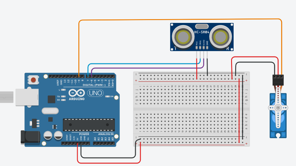
-Add a servo to the existing circuit.
-Update the existing code to control the newly added servo motor based on the distance measured by the ultrasonic sensor. The servo’s position will adjust according to the distance detected by the ultrasonic sensor.
Code:
int servoPin = 9;
int trigPin = 7;
int echoPin = 6;
long duration;
int distance;
#include <Servo.h>
Servo myServo;
void setup() {
myServo.attach(servoPin);
pinMode(trigPin, OUTPUT);
pinMode(echoPin, INPUT);
Serial.begin(9600);
}
void loop() {
digitalWrite(trigPin, LOW);
delayMicroseconds(2);
digitalWrite(trigPin, HIGH);
delayMicroseconds(10);
digitalWrite(trigPin, LOW);
duration = pulseIn(echoPin, HIGH);
distance = duration * 0.034 / 2;
Serial.print(“Distance: “);
Serial.print(distance);
Serial.println(” cm”);
if (distance < 20) { // If an object is closer than 20 cm
myServo.write(0); // Move the servo to 0 degrees
} else if (distance < 50) { // If the object is between 20 and 50 cm
myServo.write(90); // Move the servo to 90 degrees
} else {
myServo.write(180); // Move the servo to 180 degrees
}
delay(500); // Wait before taking another measurement
}
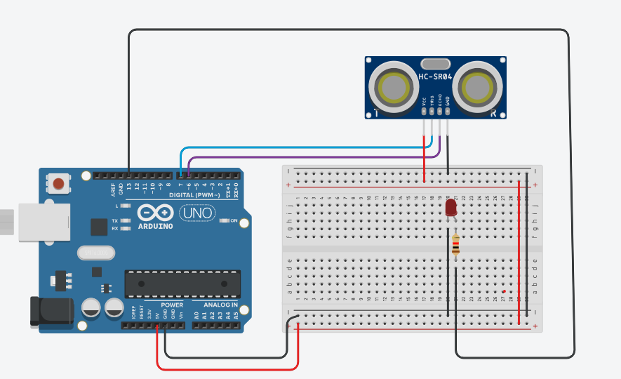
Connect the LED:
Code:
int ledPin = 13; // Pin for the LED
int trigPin = 7; // Pin for the ultrasonic sensor’s trigger
int echoPin = 6; // Pin for the ultrasonic sensor’s echo
long duration; // Variable to store the time of the echo
int distance; // Variable to store the calculated distance
void setup() {
pinMode(ledPin, OUTPUT); // Set the LED pin as an output
pinMode(trigPin, OUTPUT); // Set the trigger pin as an output
pinMode(echoPin, INPUT); // Set the echo pin as an input
Serial.begin(9600); // Initialize serial communication at 9600 baud
}
void loop() {
// Send a pulse from the trigger pin
digitalWrite(trigPin, LOW);
delayMicroseconds(2);
digitalWrite(trigPin, HIGH);
delayMicroseconds(10);
digitalWrite(trigPin, LOW);
// Measure the duration of the echo
duration = pulseIn(echoPin, HIGH);
// Calculate distance in cm
distance = duration * 0.034 / 2;
// Print distance to Serial Monitor
Serial.print(“Distance: “);
Serial.print(distance);
Serial.println(” cm”);
// Control the LED based on the distance
if (distance < 20) { // If the object is closer than 20 cm
digitalWrite(ledPin, HIGH); // Turn the LED on
} else {
digitalWrite(ledPin, LOW); // Turn the LED off
}
delay(500); // Wait half a second before taking another measurement
}
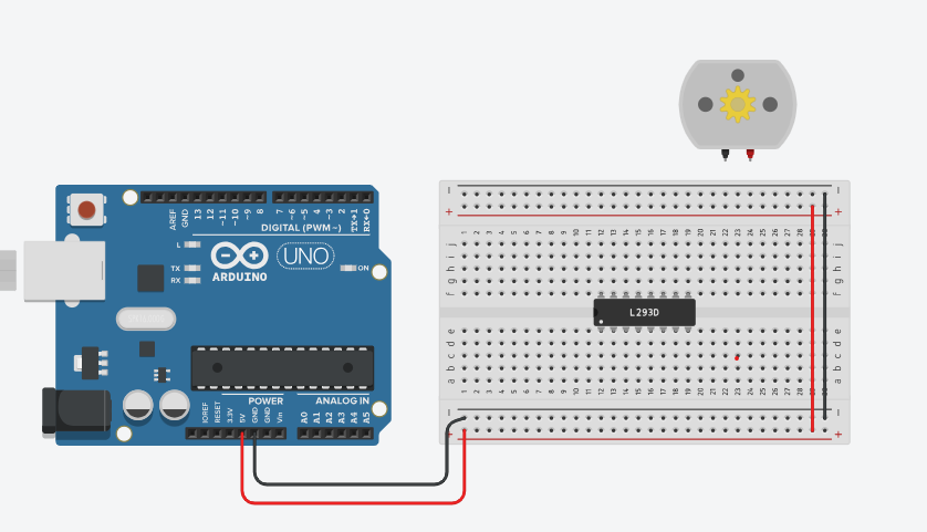
Place the motor driver on the breadboard:
Power the motor driver and breadboard:
Code:
int motorPin1 = 9; // Control pin 1 for the motor
int motorPin2 = 10; // Control pin 2 for the motor
int enablePin = 6; // PWM pin for motor speed control
void setup() {
pinMode(motorPin1, OUTPUT); // Set motor control pin 1 as an output
pinMode(motorPin2, OUTPUT); // Set motor control pin 2 as an output
pinMode(enablePin, OUTPUT); // Set the enable pin as an output
}
void loop() {
analogWrite(enablePin, 255); // Set motor speed to maximum (255)
digitalWrite(motorPin1, HIGH); // Set IN1 high
digitalWrite(motorPin2, LOW); // Set IN2 low
delay(2000); // Run the motor for 2 seconds
digitalWrite(motorPin1, LOW); // Stop the motor
digitalWrite(motorPin2, LOW); // Stop the motor
delay(2000); // Wait for 2 seconds
}
Place the push button on the breadboard:
Add a 10k ohm pull-up resistor:
code:
int motorPin1 = 9; // Control pin 1 for the motor
int motorPin2 = 8; // Control pin 2 for the motor
int enablePin = 6; // Enable pin for motor speed control
int buttonPin = 7; // Button pin
void setup() {
pinMode(motorPin1, OUTPUT); // Set motor control pin 1 as an output
pinMode(motorPin2, OUTPUT); // Set motor control pin 2 as an output
pinMode(enablePin, OUTPUT); // Set enable pin as an output
pinMode(buttonPin, INPUT_PULLUP); // Set the button pin as an input with an internal pull-up resistor
}
void loop() {
int buttonState = digitalRead(buttonPin); // Read the button state
if (buttonState == LOW) { // If button is pressed
digitalWrite(motorPin1, HIGH); // Set IN1 high to turn the motor on
digitalWrite(motorPin2, LOW); // Set IN2 low
analogWrite(enablePin, 255); // Set the motor speed to maximum (255)
} else {
digitalWrite(motorPin1, LOW); // Set both IN1 and IN2 low to stop the motor
digitalWrite(motorPin2, LOW);
analogWrite(enablePin, 0); // Turn off the motor (speed 0)
}
}
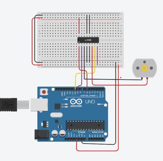
Add the second motor to the breadboard:
Connect motor driver inputs to Arduino:
code:
int motorPin1 = 9; // Control pin 1 for the first motor
int motorPin2 = 8; // Control pin 2 for the first motor
int motorPin3 = 11; // Control pin 1 for the second motor
int motorPin4 = 12; // Control pin 2 for the second motor
int enablePin1 = 6; // Enable pin for the first motor
int enablePin2 = 3; // Enable pin for the second motor
int buttonPin = 7; // Button pin
void setup() {
pinMode(motorPin1, OUTPUT); // Set motor control pin 1 for the first motor as an output
pinMode(motorPin2, OUTPUT); // Set motor control pin 2 for the first motor as an output
pinMode(motorPin3, OUTPUT); // Set motor control pin 1 for the second motor as an output
pinMode(motorPin4, OUTPUT); // Set motor control pin 2 for the second motor as an output
pinMode(enablePin1, OUTPUT); // Set enable pin for the first motor as an output
pinMode(enablePin2, OUTPUT); // Set enable pin for the second motor as an output
pinMode(buttonPin, INPUT_PULLUP); // Set the button pin as an input with an internal pull-up resistor
}
void loop() {
int buttonState = digitalRead(buttonPin); // Read the button state
if (buttonState == LOW) { // If button is pressed
// First motor control
digitalWrite(motorPin1, HIGH); // Set IN1 high to turn the first motor on
digitalWrite(motorPin2, LOW); // Set IN2 low for the first motor
analogWrite(enablePin1, 255); // Set the first motor speed to maximum
// Second motor control
digitalWrite(motorPin3, HIGH); // Set IN3 high to turn the second motor on
digitalWrite(motorPin4, LOW); // Set IN4 low for the second motor
analogWrite(enablePin2, 255); // Set the second motor speed to maximum
} else {
// Stop both motors
digitalWrite(motorPin1, LOW); // Set both IN1 and IN2 low to stop the first motor
digitalWrite(motorPin2, LOW);
analogWrite(enablePin1, 0); // Stop the first motor
digitalWrite(motorPin3, LOW); // Set both IN3 and IN4 low to stop the second motor
digitalWrite(motorPin4, LOW);
analogWrite(enablePin2, 0); // Stop the second motor
}
}
// MOTOR 1
int motor1enA = 9; // PWM Speed Control (ENA connected to pin 9)
int motor1in1 = 8; // Direction Control (IN1 connected to pin 8)
int motor1in2 = 7; // Direction Control (IN2 connected to pin 7)
// MOTOR 2
int motor2enB = 10; // PWM Speed Control (ENB connected to pin 10)
int motor2in3 = 6; // Direction Control (IN3 connected to pin 6)
int motor2in4 = 5; // Direction Control (IN4 connected to pin 5)
// Serial Communication
int state;
void setup() {
// Start serial communication
Serial.begin(9600);
// MOTOR 1 OUTPUTS
pinMode(motor1enA, OUTPUT);
pinMode(motor1in1, OUTPUT);
pinMode(motor1in2, OUTPUT);
// MOTOR 2 OUTPUTS
pinMode(motor2enB, OUTPUT);
pinMode(motor2in3, OUTPUT);
pinMode(motor2in4, OUTPUT);
// Set initial motor speed
analogWrite(motor1enA, 100); // Set speed (0-255)
analogWrite(motor2enB, 100); // Set speed (0-255)
}
// Function to start both motors (forward direction)
void startMotors() {
digitalWrite(motor1in1, HIGH);
digitalWrite(motor1in2, LOW);
digitalWrite(motor2in3, HIGH);
digitalWrite(motor2in4, LOW);
}
// Function to stop both motors
void stopMotors() {
digitalWrite(motor1in1, LOW);
digitalWrite(motor1in2, LOW);
digitalWrite(motor2in3, LOW);
digitalWrite(motor2in4, LOW);
}
void loop() {
// Serial control for starting and stopping motors
if (Serial.available() > 0) {
state = Serial.read();
if (state == ‘S’) {
Serial.println(“Stop Motors”);
stopMotors();
} else if (state == ‘F’) {
Serial.println(“Start Motors”);
startMotors();
}
}
}
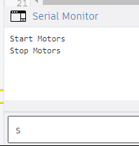
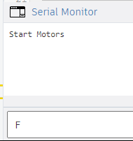
-Open the Serial Monitor:
Click on the Serial Monitor button (magnifying glass icon) located in the top right corner of the Arduino IDE, or go to Tools > Serial Monitor.
-Control the DC Motors via Serial Monitor
In the Serial Monitor, you can type characters to control the motors:
Type F (for “Forward”) and press Enter: The motors will start moving forward, as defined by the startMotors() function.
Type S (for “Stop”) and press Enter: The motors will stop, as defined by the stopMotors() function.
-Update the code to handle new commands for enhanced motor control.
// MOTOR 1
int motor1enA = 9; // PWM Speed Control (ENA connected to pin 9)
int motor1in1 = 8; // Direction Control (IN1 connected to pin 8)
int motor1in2 = 7; // Direction Control (IN2 connected to pin 7)
// MOTOR 2
int motor2enB = 10; // PWM Speed Control (ENB connected to pin 10)
int motor2in3 = 6; // Direction Control (IN3 connected to pin 6)
int motor2in4 = 5; // Direction Control (IN4 connected to pin 5)
// Serial Communication
int state;
void setup() {
// Start serial communication
Serial.begin(9600);
// MOTOR 1 OUTPUTS
pinMode(motor1enA, OUTPUT);
pinMode(motor1in1, OUTPUT);
pinMode(motor1in2, OUTPUT);
// MOTOR 2 OUTPUTS
pinMode(motor2enB, OUTPUT);
pinMode(motor2in3, OUTPUT);
pinMode(motor2in4, OUTPUT);
}
// Function to set motor speed and enable them
void startMotors() {
// Set motor speeds (range: 0 – 255)
analogWrite(motor1enA, 100); // Motor 1 speed
analogWrite(motor2enB, 100); // Motor 2 speed
Serial.println(“Motors started”);
}
// Function to move forward
void forward() {
digitalWrite(motor1in1, HIGH);
digitalWrite(motor1in2, LOW);
digitalWrite(motor2in3, HIGH);
digitalWrite(motor2in4, LOW);
}
// Function to move backward
void backward() {
digitalWrite(motor1in1, LOW);
digitalWrite(motor1in2, HIGH);
digitalWrite(motor2in3, LOW);
digitalWrite(motor2in4, HIGH);
}
// Function to turn left (by rotating only Motor 1)
void left() {
digitalWrite(motor1in1, HIGH);
digitalWrite(motor1in2, LOW);
digitalWrite(motor2in3, LOW);
digitalWrite(motor2in4, LOW);
}
// Function to turn right (by rotating only Motor 2)
void right() {
digitalWrite(motor1in1, LOW);
digitalWrite(motor1in2, LOW);
digitalWrite(motor2in3, HIGH);
digitalWrite(motor2in4, LOW);
}
// Function to stop both motors
void stopM() {
digitalWrite(motor1in1, LOW);
digitalWrite(motor1in2, LOW);
digitalWrite(motor2in3, LOW);
digitalWrite(motor2in4, LOW);
}
void loop() {
// Check if there is serial input
if (Serial.available() > 0) {
state = Serial.read(); // Read the input character
// Motor control based on serial input
if (state == ‘T’) {
Serial.println(“Start Motors”);
startMotors();
} else if (state == ‘F’) {
Serial.println(“Go Forward”);
forward();
} else if (state == ‘B’) {
Serial.println(“Go Backward”);
backward();
} else if (state == ‘L’) {
Serial.println(“Go Left”);
left();
} else if (state == ‘R’) {
Serial.println(“Go Right”);
right();
} else if (state == ‘S’) {
Serial.println(“Stop”);
stopM();
}
}
}
Send Commands: Type one of the following commands in the input field and press Enter:
‘T’: Start the motors at the initial speed.
‘F’: Move the motors forward.
‘B’: Move the motors backward.
‘L’: Turn left by rotating Motor 1.
‘R’: Turn right by rotating Motor 2.
‘S’: Stop both motors.
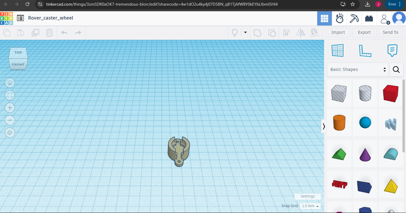
Objective:This lesson will cover the fundamentals of 3D design using Tinkercad and introduce the basics of 3D printing. Participants will learn how to create and manipulate 3D models in Tinkercad, equipping them with the skills needed for real-world 3D printing applications.
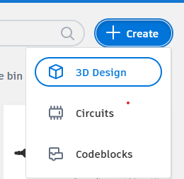
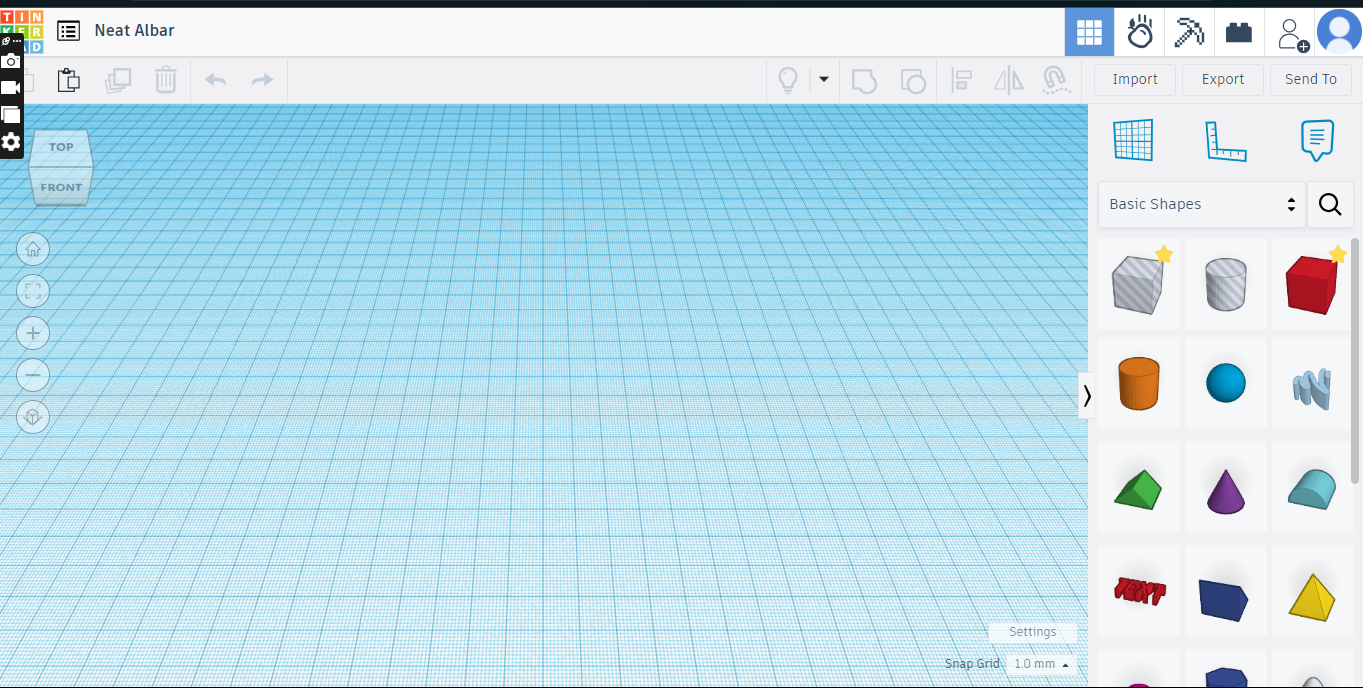
-Open Tinkercad and navigate to the “3D Design” section.
-Explore the Tinkercad 3D interface and its basic tools.
-Overview of basic functions:

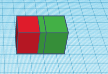
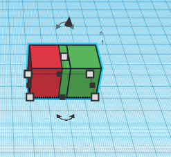
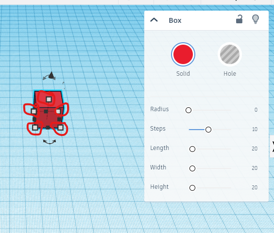
-Create basic shapes like cubes, cylinders, and spheres.
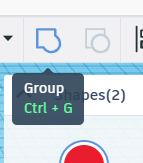
-Modify shapes by resizing, rotating, and combining them.
-Experiment with color and alignment.
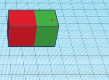
Design a simple object such as a keychain with your name
You can select only one option
Continue experimenting with your design.
-Add details or combine shapes creatively.
-Explore different design possibilities and make changes as needed.
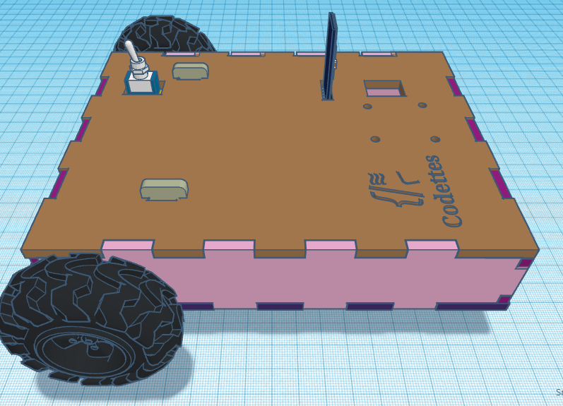
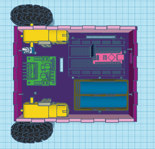
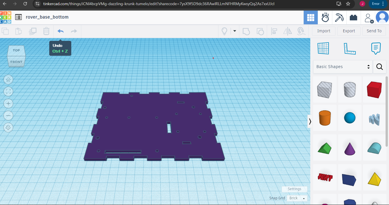
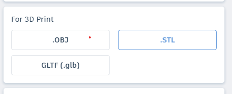
Objective: Students will download the necessary SVG and STL files from Tinkercad, prepare them for laser cutting and 3D printing, and assemble the components to build a functioning rover.
Complete rover design:
Rover_base_bottom (I will be using this one).
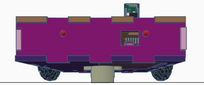
Objective: In this lesson, you will start by preparing for prototyping by reviewing components and instructions and understanding the prototyping process. You will then assemble 3D-printed components with electronic parts, build the circuit based on the schematic, and upload and test their Arduino code. The next steps include integrating the circuit with the rover enclosure, performing initial tests, and completing the final assembly. Finally, you will prepare your projects for presentation, discuss key features and design choices, and wrap up by reviewing the integration of code, electronics, and design, emphasizing the role of prototyping.
-Review the provided components and instructions.
-Brief overview of the prototyping process and how to follow the steps.
-Follow the instructions to assemble the pre-cut rover enclosure with the provided electronic components.
-Ensure all parts fit together correctly and securely.
-Build the circuit as instructed using the provided components.
-Connect the circuit components according to the provided schematic.
-Open the Arduino IDE and upload the provided code to the Arduino board.
-Make sure the code is running correctly and troubleshoot any issues with the circuit or code.
-code:
// MOTOR 1
int motor1enA = 5; // PWM Speed Control
int motor1in1 = 4; // Direction Control
int motor1in2 = 2; // Direction Control
// MOTOR 2
int motor2enB = 3; // PWM Speed Control
int motor2in3 = 7; // Direction Control
int motor2in4 = 12; // Direction Control
// Serial Communication
int state;
void setup() {
// Start serial communication
Serial.begin(9600);
// MOTOR 1 OUTPUTS
pinMode(motor1enA, OUTPUT);
pinMode(motor1in1, OUTPUT);
pinMode(motor1in2, OUTPUT);
// MOTOR 2 OUTPUTS
pinMode(motor2enB, OUTPUT);
pinMode(motor2in3, OUTPUT);
pinMode(motor2in4, OUTPUT);
}
// Function to start both motors at an initial speed
void startMotors() {
// Set motor speeds (range: 0 – 255)
analogWrite(motor1enA, 100); // Motor 1 speed
analogWrite(motor2enB, 100); // Motor 2 speed
Serial.println(“Motors started”);
}
void forward() {
// Set both motors to move forward
digitalWrite(motor1in1, HIGH);
digitalWrite(motor1in2, LOW);
digitalWrite(motor2in3, HIGH);
digitalWrite(motor2in4, LOW);
}
void backward() {
// Set both motors to move backward
digitalWrite(motor1in1, LOW);
digitalWrite(motor1in2, HIGH);
digitalWrite(motor2in3, LOW);
digitalWrite(motor2in4, HIGH);
}
void left() {
// Move left by rotating only Motor 1
digitalWrite(motor1in1, HIGH);
digitalWrite(motor1in2, LOW);
digitalWrite(motor2in3, LOW);
digitalWrite(motor2in4, LOW);
}
void right() {
// Move right by rotating only Motor 2
digitalWrite(motor1in1, LOW);
digitalWrite(motor1in2, LOW);
digitalWrite(motor2in3, HIGH);
digitalWrite(motor2in4, LOW);
}
void stopM() {
// Stop both motors
digitalWrite(motor1in1, LOW);
digitalWrite(motor1in2, LOW);
digitalWrite(motor2in3, LOW);
digitalWrite(motor2in4, LOW);
}
void loop() {
// Check if there is serial input
if (Serial.available() > 0) {
state = Serial.read(); // Read the input character
// Motor control based on serial input
if (state == ‘T’) {
Serial.println(“Start Motors”);
startMotors();
} else if (state == ‘F’) {
Serial.println(“Go Forward”);
forward();
} else if (state == ‘B’) {
Serial.println(“Go Backward”);
backward();
} else if (state == ‘L’) {
Serial.println(“Go Left”);
left();
} else if (state == ‘R’) {
Serial.println(“Go Right”);
right();
} else if (state == ‘S’) {
Serial.println(“Stop”);
stopM();
}
}
}
-Integrate the assembled circuit with the rover enclosure.
-Ensure all components are properly secured and functioning within the enclosure.
-Perform initial testing to ensure the prototype works as expected.
-Make any necessary adjustments to the design, code, or circuit.
-Complete the final assembly of the prototype, ensuring all components are properly integrated and securely in place.
-Conduct a final test to confirm the prototype is working as intended.
Having trouble? Let us know by completing the form below. We'll do our best to get your issues resolved quickly.
"*" indicates required fields